In this lesson, you will get to see the bare bones. I am going to show you more details regarding the headers used in encapsulation and de-encapsulation process. Also, we will consider a typical transmission to shed more light on somewhat 'dry' content of the previous two lessons.
As mentioned before, the application layer on the client computer is sending some data (request that will look differently depending on the applications used) destined to the application on the server computer. A detailed explanation of what happens during the transmission can be found in the free, on-line 'TCP/IP Guide' book. The link is available below. However, the above guide is a hefty book. If you want to stick to the basics please, keep on reading.
http://www.tcpipguide.com/free/t_toc.htm
All transmissions use similar process so, as an example, I'm going to show you a typical web client to web server transmission step-by-step. The methodology is almost identical for all other types of data exchange. Before I do that though, please familiarize yourself with the headers that will be used during the encapsulation (sender) and de-encapsulation (receiver) process. Do NOT dwell on those, or try to understand all the mentioned fields. Instead, take a brief look, and refer to them while reading the lesson.
Transport Layer Headers (layer 4)
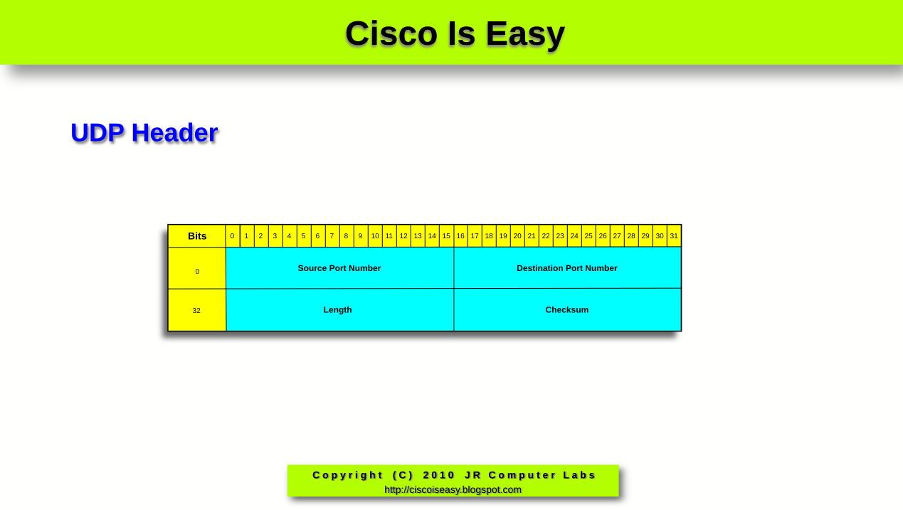
Pic. 1 - UDP Header (used mostly in voice/video transmissions/dns queries, etc.)

Pic. 3 - IP Header

Data-Link Layer Header (layer 2)
Pic. 4 Ethernet Header (most commonly used technology in our LAN networks)


Click on the pictures to enlarge them.
NOTICE!
The following discussion has been simplified in order to help you understand the general process. Keep in mind that in reality, it is much more complex process than the explanation presented below.
The best way to learn the theory is to see things working in practice. That is why, I am going to capture the web traffic initiated by my client computer destined to my web server. Before you delve into analyzing the details, please familiarize yourself with my client and server addresses first.
Web Client Details:
IP Address: 192.168.1.13 255.255.255.0
MAC Address: 00:24:e8:fa:07:1a
Web Server Details:
IP Address: 192.168.1.1 255.255.255.0
MAC Address: 00:50:bf:9c:45:6a
Step 1
In the URL field of my web browser I'm typing in the address of the server using HTTP protocol (Layer 7-5 protocol used as an example). This will tell the application what the address of the server is. I accept it by hitting the 'Enter' key.
Pic. 5 - URL Address of the web server
NOTICE!
The following discussion has been simplified in order to help you understand the general process. Keep in mind that in reality, it is much more complex process than the explanation presented below.
Web Client to Web Server Transmission Step-by-Step
The best way to learn the theory is to see things working in practice. That is why, I am going to capture the web traffic initiated by my client computer destined to my web server. Before you delve into analyzing the details, please familiarize yourself with my client and server addresses first.
Web Client Details:
IP Address: 192.168.1.13 255.255.255.0
MAC Address: 00:24:e8:fa:07:1a
Web Server Details:
IP Address: 192.168.1.1 255.255.255.0
MAC Address: 00:50:bf:9c:45:6a
Step 1
In the URL field of my web browser I'm typing in the address of the server using HTTP protocol (Layer 7-5 protocol used as an example). This will tell the application what the address of the server is. I accept it by hitting the 'Enter' key.
Pic. 5 - URL Address of the web server

Step 2
The client computer realizes that the address of the recipient (web server) is in the same layer 3 network (the first 24 bits of the both source and destination address are the same). More on this, you will learn in the upcoming lessons. As a result of that, the client needs to obtain the MAC address of the web server first. Recall from the previous lesson that IP packet is encapsulated in layer 2 header, which in our case uses source and destination MAC addresses. Normally, the client computer is going to check the local 'arp cache' to find out if the mapping of the destination IP address to its MAC address is there. If not, like in my example, the client is going to issue 'ARP Request' message (Address Resolution Protocol) to learn the destination's computer MAC address. This request is propagated to ALL local machines in the network 192.168.1.0/24. Pay attention to the highlighted lines in the picture. The destination MAC address in the query is the Ethernet broadcast address: FF:FF:FF:FF:FF:FF. In the ARP request the client computer asks 192.168.1.1 for its MAC address (which, as of right now, is all 0s; see the below pic. 6).
Pic. 6 - ARP Request

NOTICE!
The ARP request is considered a layer 2 protocol. It is directly encapsulated in the Ethernet II frame. Its header is presented in the second line in the middle panel (under the 'Frame 3').
Step 3
There is only one computer with its unique address of 192.168.1.1 in the network. This one replies to the query with the 'ARP Reply' message back to the sender of the request, telling it what the MAC address it uses. The address is seen in the middle of the pic. 7 (highlighted) belongs to web server. The address reads:
00:50:bf:9c:45:6a
Pic. 7 - ARP Reply

Step 4
The MAC address of the web server was the missing piece of information the client needed to proceed with the TCP session establishment. TCP, being a session-oriented and reliable transport protocol, must establish the mutual communication with the web server first, before it is allowed to send the data from the web browser. This is known as the 3-way handshake. Let us look at the details of the first TCP segment in this session establishment phase.
1. The client (192.168.1.13) sends an 'empty' TCP segment (i.e. with no data from the application included in it).
- It chooses a random source port number first. In the transmission presented the TCP Src-Port: 51504 is chosen. Also it uses the Dst-Port: 80 which identifies web server destination application. This pair of ports will uniquely identify this particular transmission, as the client can initiate multiple transmissions at the same time. Those two ports (source and destination port numbers) allow multiple transmissions without a risk of 'mixing up' which reply from the servers should be sent back to which inititiating that request process. This way, the process that initiated transmission is going to receive the right reply. I need to add here that TCP and UDP ports are divided into two major groups: 'well-known ports' which are ports between 1-1023 (always destination ports for the client initiating transmissions), and 'ephemeral ports' between 1024-65535 numbers. The latter ones, clients choose randomly to mark the source process for their transmissions.
- Sequence Number in the segment = 0. If the web server (destination) receives this segment and replies to it, it will put a value of 1 in the Acknowledgment field. That is an indication for the client, that the first segment did arrive successfully at the server.
- The SYN flag = 1, and all the rest of the flags are set to 0. It means,that this is the first handshake in the exchange. It is the client's request to establish session with the server.
NOTICE!
The layer 4 segment has been encapsulated in the layer 3 header (pic. 8: 'Internet Protocol') and further encapsulated in the Ethernet frame (pic. 8: Ethernet II). The first line in the middle section of the picture, is what is seen on the wire.
Pic. 8 - TCP Syn Segment

2. The next segment captured (pic. 9) comes from the web server and is the reply for the 'SYN' message sent by the web client. Now, please compare both pictures (pic. 8 and pic. 9). Pay attention to the source and the destination TCP port numbers, and the source and destination addresses used in the layer 3 (IP header) and the layer 2 (Ethernet header). Did you notice they are reversed now?
- TCP port numbers are now reversed (TCP Src-port=80, Dst-port=51504) in order to send the reply directly to the port that initiated the request).
- The server's segment has the Sequence number=0, but the Acknowledgement number=1. It is what we expected. This means that the delivery of the client's first segment was successful).
- The flag ACK=1, which is the acknowledgement for the SYN flag from the client.
- The server also wants to synchronize the transmission with the client. That is why it sets its own SYN=1 in this segment.
Pic. 9 - Server's response SYN, ACK

3. The client needs to reply to the server's SYN message with its ACK=1 to finalize the session establishment (see the pic. 10). Here's what you find in the third handshake from the web client:
- Src-port=51504, Dst-port=80.
- Acknowledgement=1, which is to tell the server that its segment sequence=0 has arrived successfuly.
- Sequence=1, which means that it is the second segment sent to the server. That's what the server expects to receive (in the next reply from the server, it should see Acknowledgment=2).
- The flag ACK=1, which is the response to the SYN=1 flag received from the server.
Pic. 10 - Final ACK from the server

Step 5
The client has established session with the server, so now it sends the first DATA packet (GET request), asking the server for its main page (look at pic. 11).
Pic. 11 - Request from the client web browser

NOTICE!
The data from the client (GET) is encapsulated in the layer 4 header, this in turn is encapsulated in the layer 3 header, and the whole thing further encapsulated in the layer 2 header. It is what I described in the lesson 5. See the details in the pic. 11.
Step 6
Finally, the reply comes back from the server to the client with the html page (see the pic. 12).
Pic. 12 - Reply from the web server

One last thing, I would like to bring up here. Since the appropriate layer understands its header (TCP-talks-to-TCP, IP-talks-to-IP, Ethernet-talks-to-Ethernet), we have two different inter-layer communications taking place:
- Vertical communication occurs when the upper layer is sending something to the lower layer and vice versa.
- Horizontal (virtual) communication between hosts when the destination host reads the appropriate header encapsulated by the sender.
Pic. 13 - Horizontal and vertical inter-layer communication.


