Lab pre-requisites:
Lab 2-1 Packet Tracer Topology Download.
Topology Diagram
In this lab there are four tasks that allow apply a basic security on IOS based switches and routers.
Task 1: Device password protection.
Task 2: Remote access using Telnet and SSH.
Task 3: Limiting remote access based on source IP Addresses.
Task 4: Creating a login banner page.
Let's rock and roll!
Task 1: Device password protection.
As an example let's protect access to SW1 starting at protecting the console which by default allows access without any password.
Notice
Switches and routers allow access to the console without prompting for the password. There is 'no login' keyword applied on the by default which means that a user is not prompted for the password even if one is configured. In order to protect the console, you must apply both password and 'login' keyword in order to prompt the user for the password.
SW1 Console Password (use cisco as password):
SW1>enable
SW1#conf t
Enter configuration commands, one per line. End with CNTL/Z.
SW1(config)#line con 0
SW1(config-line)#password cisco
SW1(config-line)#login
SW1(config-line)#
In order to verify this configuration exit session by first typing end and then exit. You will be prompted for the password while creating new console session.
As of now, we only protected console access. We must also protect the privileged exec mode (enabled mode). Let's use password sanfran for a change. The command should be applied in the global configuration mode (if you are still in the console prompt, type in exit to go back to global config mode).
SW1(config)#enable password sanfran
SW1(config)#
Now, if you try to login to enabled mode the system will ask you for password sanfran to grant you access.
The problem is that all the passwords are now showing in clear text format. Check this out:
In order to protect all the existing passwords and the ones you will add in the future, we can encrypt them using Type-7 algorithm known as 'over-shoulder' encryption.
Let's turn on the service now, using global configuraition command as shown below:
SW1(config)#service password-encryption
SW1(config)#
All the passwords are not showing as clear text any more. However, you must still be careful not to disclose those encrypted strings as they can be easily broken on the net. As an example, copy the string below that my system used for sanfran:
08324D400F0B0419
Open the web page below and paste the string into Type-7 box and click 'Crack Password'. See for yourself.
However, this protection is making difficult for a person to guess our password while looking at our screen when we display running-config.
It is much smarter to protect our enabled mode, using a properly encrypted password (either MD5 or SHA-256 will be used dependent of the platform). Let's also use password cisco to do it.
SW1(config)#enable secret cisco
SW1(config)#
Now, let's see what encryption Packet Tracer applied:
Since we have both: enable password (sanfran) and enable secret applied, the question is which password is the system going to use upon our attempt to enter 'enabled mode'? The answer is, the password that is more secure (secret). The only problem is that using secret method we can only protect enabled mode but not console or vty lines (used for remote access). We will handle this as our last thing in this lab.
Lastly, in this task let's allow remote access using Telnet. Here's the basic configuration (password cisco again, although on the production equipment each mode such as console, vty, enabled, should have different passwords).
Let's see if we try to access switch (vty lines) using telnet, what happens when login keyword is applied but there is no password used as shown below:
!
line vty 0 4
login
line vty 5 15
login
!
Notice
At the moment, my PC1 has IP Address: 10.1.1.100/24.
SW1 has VLAN1 interface configured with IP Address: 10.1.1.11/24
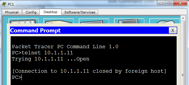
My Telnet session from PC1 results in the following:
Notice
On a real equipment we receive the message:
password required but none set
Task 2: Remote access using Telnet and SSH.
If we want basic connectivity, assigning password to the first set of vty lines (0-4) can allow up to 5 simultaneous Telnet connections (if more is required apply password on vty lines 5 15 etc.)
SW1(config)#line vty 0 4
SW1(config-line)#password cisco
SW1(config-line)#
Now, Telnet works!
Notice
When you choose password for the production equipment, make sure that they are long (at least 8 characters) and not dictionary keywords. Use upper and lower case with special characters (such as %, ^, & etc.).
However, from security perspective, Telnet connections are not recommended as everything we type (that includes the password) are sent in clear text format. If intercepted, we're in trouble.
SSH connections are highly recommended. Let's allow SSH support for our remote connections to SW1. These are necessary steps:
Notice
In real network it is recommended to have a centralized login access solution (using AAA server). Here, only local protection is used.
Step 1
Create username and password on the local device (user: ccna, password: cisco)
SW1(config)#username ccna secret cisco
SW1(config)#
Notice
If you want the user account (here ccna) to have access to privileged mode automatically upon connection to vty lines (skipping 'user exec mode'), you can use this instead:
SW1(config)#username ccna privilege 15 secret cisco
SW1(config)#
Step 2
Configure domain name (here cisco.com).
Without domain name RSA public/private keys cannot be generated (command is rejected)
SW1(config)#ip domain name cisco.com
SW1(config)#
Step 3
Generate Public/Private key pair used for encryption/decryption of our transmissions while remotely accessed using SSH. Apply key 1024 bit when asked for modulus.
SW1(config)#crypto key generate rsa
The name for the keys will be: SW1.cisco.com
Choose the size of the key modulus in the range of 360 to 2048 for your
General Purpose Keys. Choosing a key modulus greater than 512 may take
a few minutes.
How many bits in the modulus [512]: 1024
% Generating 1024 bit RSA keys, keys will be non-exportable...[OK]
SW1(config)#
Step 4
Change SSH session version to allow only SSHv2 connection (default 1.99 allows both SSHv1 and SSv2).
Default:
SW1(config)#ip ssh version 2
SW1(config)#
After the change:
Step 5
Allow SSH acces.
SW1(config)#line vty 0 4
SW1(config-line)#transport input ssh
SW1(config-line)#login local
SW1(config-line)#
Notice
The command: transport input ssh, only allows ssh. You can add telnet as well but in my opinion that defeats the purpose of this lab.
Also, the command: login local, allows system to use locally defined user (ccna) to log on.
You can verify this configuration by ssh-ing to itself (notice: -l for login not number 1 below):
SW1#
SW1#ssh -l ccna 10.1.1.11
Exit upon verification
Task 3: Limiting remote access based on source IP Addresses.
As an example let us allow PC1 (IP Address 10.1.1.100) to access SW1 using SSH but no other source IP address.
SW1(config)#access-list 5 permit 10.1.1.100
SW1(config)#line vty 0 4
SW1(config-line)#access-class 5 in
SW1(config-line)#
Notice
The last 'implicit' rule says deny any. That means that no other source IP address can get access to vty lines (ssh/telnet).
On real equipment you could add the following ACL statement
SW1(config)#access-list 5 deny any log
Unfortunately, this 'log' option does not work in Packet Tracer.
Task 4: Creating a login banner page.
Notice
Banner in Packet tracer only supports motd option (banner login does not work)
SW1(config)#banner motd &
Enter TEXT message. End with the character '&'.
*************************************************
* Unauthorized Access Strictly Prohibited! *
* ***********************************************
&
SW1(config)#
Notice
Make sure that you start banner with a delimiting character that is not used in the banner itself (I could not use '*' as a delimiting character). You must end with the same character to mark the ending of the message to be displayed upon connection.
Verification
Since only PC1 can access SW1 remotely I added telnet support (no ssh client on PC1) to see the banner upon connection.
SW1(config)#line vty 0 4
SW1(config-line)#transport input all
SW1(config-line)#
The last "security" touch is to use username and password for console 0 access. Since we have username and password locally defined (ccna/cisco), let's use it:
SW1(config)#line con 0
SW1(config-line)#login local
SW1(config-line)#