All Cisco routers have the routing capability turned ON by default. The command responsible for this is:
router(config)#ip routing
This allows a router to create and use the routing table the moment we enable and configure at least two interfaces.
NOTICE!
Some subnets and networks are simulated by means of creating and configuring virtual interfaces (Loopback) in my topology.
Pic. 1 - Routing Topology 1


Icons designed by: Andrzej Szoblik - http://www.newo.pl
Directly Connected Networks
In the topology used (pic. 1), the routers have been assigned IP addresses and the interfaces are up. Since the routing process is enabled (ip routing) the directly connected subnets/networks show in the routing table immediately. Look at R1's routing table:
Pic. 2 - Directly Connected Networks.

- Applying static routing (manual method)
- Applying dynamic routing (a routing protocol that distributes information automatically)
Static Routing
There are pros and cons of using manual method. In complex scenarios (with redundant connections), more often than not, we use dynamic routing protocols. But there are situations in which static routing is good or perhaps the best solution.
Consider our example. R4 and R5 are connected to so called stub networks. A stub network has only one way in and out (one path). Some routers used in such designs are relatively cheap and may not even have enough hardware resources to run a dynamic routing protocol (such as OSPF or EIGRP). Then, installing static routes is the only option possible. Also, imagine your broadband router (your home network is also the stub-like if you're connected to one ISP). This router does not have the paths to each and every destination on the Internet. It uses a form of static route instead known as: default route. More on the default route later in the post.
Let's look at the syntax which allows us to instruct a router about remote networks and subnets manually.
 Let's read what this command does.
Pic. 3 - Static Route Command Version 1.

"IP route towards class C network 192.168.1.0/24 can be reached by sending packets to a next-hop router out the serial0/2 interface."
The last parameter used shows the router which interface should be used to send the packets out. If you configure the outbound interface instead of the IP address of the next-hop router in the path, this connection must be point-to-point (not multiaccess).
In case, the router's egress (outbound) interface is multiaccess link (Ethernet, Frame-Relay, ATM etc.), we must NEVER use local interface but IP address of the next-hop router instead. If you do not follow this recommendation, the router will try to resolve the layer 3 to layer 2 address for every destination out that interface. This leads to serious inefficiency and shows little understanding of routing operation of a person who used it.
If the router must send the packet to the next router in order to get to the destination (egress interface is multiaccess), the 'ip route' command should look like the example below (pic. 4).
Pic. 4 - Static Route Command Version 2.

Let's configure our routers so they can reach all networks int the topology used (pic. 1).
NOTICE!
The routing works in both directions. This means that the router receiving packet to its directly connected network/subnet must know the returning path to the sender of the packet (source).
Configuration on R1
Reachability towards 172.31.2.0/24. The next-hop router is R2. The outbound interface is multiaccess link (F1/0). The order of statements does not matter. Configuring the remaining routers I will use a more logical approach than on R1.
R1#configure terminal
R1(config)#ip route 172.31.2.0 255.255.255.0 172.31.123.2
R1(config)#
Step 2
Reachability towards 172.31.3.0/28 and 172.31.16.0/28. The same egress interface (F1/0).
R1(config)#ip route 172.31.3.0 255.255.255.240 172.31.123.3
R1(config)#ip route 172.31.3.16 255.255.255.240 172.31.123.3
R1(config)#
Step 3
Reachability towards 192.168.4.0/24. The egress interface is point-to-point (S0/2 running HDLC protocol). I can use either the next-hop IP address or the local interface s0/2.
R1(config)#ip route 192.168.4.0 255.255.255.0 s0/2
R1(config)#
Step 4
In order to reach Branch2 network 192.168.5.0/24, R1 must use R2 as the gateway. Even though R2 does not know how to get there now, I will configure it and then configure R2 to reach all networks and subnets (including 192.168.5.0/24).
R1(config)#ip route 192.168.5.0 255.255.255.0 172.31.123.2
R1(config)#
Step 5
Reachability to the point-to-point subnet between R2 and R5 (172.31.25.0/24).
R1(config)#ip route 172.31.25.0 255.255.255.0 172.31.123.2
R1(config)#
Now, let's see what the routing table reveals:
Pic. 5 - Routing Table of R1.

Before I proceed with the configuration of the other routers let's consider a few things.
Look at the R1's routing table and the topology carefully, and try to answer the following questions before you test the reachability using 'ping'. If you have problems answering the questions 1, the remaining ones (2-4) should give you a few hints.
Question 1
How many IP addresses presented in the topology (pic. 1) will respond to ping from R1 after you have configured static routes so far (only R1 is configured with static routes; all other routers have IP addresses and interfaces enabled)?
Question 2
R1 sends ping (echo request) towards 192.168.4.1. What is going to be the source IP address of this request?
Question 3
R1 sends ping (echo request) towards 172.31.25.2. Is R1 going to receive reply (echo reply)? Why?
Question 4
R1 sends ping (echo request) towards 172.31.25.5. Is R1 going to receive reply (echo reply)? Why?
If you have answered them, check if you were right. The answers are as follows.
Answer 1
There are 11 IP addresses to respond to the ping sent by R1. These are:
- 172.31.1.1 - reason: directly connected subnet (Loopback 1).
- 172.31.123.1 through 3 - reason: directly connected subnet (F1/0).
- 172.31.3.1 and 172.31.3.17 - reason: source IP address is the 172.31.123.1. It's the egress interface to reach these two addresses (via F1/0). R3 knows how to get back to R1's F1/0 interface (R3's F1/0 is connected to 172.31.123.0/24 too).
- 172.31.2.1 and 172.31.25.2 - reason: R1 will use F1/0 (egress interface) to reach these IP addresses according to our 'ip route' statements. The source IP address is going to be the address of F1/0. R2 knows its way back to 172.31.123.0/24 subnet (directly connected to F1/0).
- 172.31.14.1, 172.31.14.4 and 192.168.4.1 - reason: R4 knows how to get back to the source IP address R1 uses for these destination. R1 uses 172.31.14.1 as the source IP address. This source (subnet 172.31.14.0/24) is shared between R1 and R4 on their Serial0/2 interfaces.
- A router is going to find the best match in the routing table for each destination. If not found, of course the packet is dropped. If found though, a router will not change the source and destination addresses in packets TRAVERSING it. If the packet is ORIGINATED by the router (here: ping), the source of IP address used is going to be the address of its egress (outbound) interface by default.
- Sending a packet out is one job, but the destination will try to send a response back to the source. The remote router which is going to respond, must know how to reach the source of the transmission as well (valid path back to the source in its routing table).
Ping from R1 towards 192.168.4.1 is going to use 172.31.14.1 as its source address since according to the routing table Serial0/2 is the outbound interface.
Destination 192.168.4.1 shows the following detailed output on R1:
Pic. 6 - R1's Route Towards 192.168.4.1.

The route shows that the longest match for 192.168.4.1 is: 192.168.4.0/24. This routing table entry points to Serial0/2 as an egress interface.
Answer 3
R1 sends the ping (echo request) packet towards 172.31.25.2. Like explained in the answer 2, the source IP address for this echo request is going to be the address of the outbound interface (FastEthernet1/0). R2 knows how to reply back to 172.31.123.1 since R2 is directly connected to the subnet 172.31.123.0/24 with its FastEthernet1/0 interface.
Answer 4
R1 sends the ping (echo request) packet towards 172.31.25.5. It is NOT going to get the reply from R5. The reason is that R5 does not know how to reply back to the source (172.31.123.1). It has not been configured to reach remote subnets and networks yet.
I hope you have found this little quiz entertaining and informative enough.
Would you know how to configure R2 and R3 using R1's configuration as an example? Give it a try. If you can't do it yet, just follow the configuration presented below.
Configuration on R2
Step 1
Reachability to networks/subnets via R1.
R2#configure terminal
R2(config)#ip route 172.31.1.0 255.255.255.0 172.31.123.1
R2(config)#ip route 172.31.14.0 255.255.255.0 172.31.123.1
R2(config)#ip route 192.168.4.0 255.255.255.0 172.31.123.1
R2(config)#
Step 2
Reachability to networks/subnets via R3.
R2(config)#ip route 172.31.3.0 255.255.255.240 172.31.123.3
R2(config)#ip route 172.31.3.16 255.255.255.240 172.31.123.3
R2(config)#
Step 3
Reachability to network via R5.
R2(config)#ip route 192.168.5.0 255.255.255.0 s0/2
R2(config)#
Configuration on R3
Step 1
Reachability to networks/subnets via R1.
R3#configure terminal
R3(config)#ip route 172.31.1.0 255.255.255.0 172.31.123.1
R3(config)#ip route 172.31.14.0 255.255.255.0 172.31.123.1
R3(config)#ip route 192.168.4.0 255.255.255.0 172.31.123.1
Step 2
Reachability to networks/subnets via R2.
R3(config)#ip route 172.31.2.0 255.255.255.0 172.31.123.2
R3(config)#ip route 172.31.25.0 255.255.255.0 172.31.123.2
R3(config)#ip route 192.168.5.0 255.255.255.0 172.31.123.2
R3(config)#
As for the routers R4 and R5 they connect stub networks. In order to simplify the configuration on these and reduce the number of entries on them, I am going to use a special type of static route called: the default route.
Pic. 7 - Default Route Example.

The destination IP address 0.0.0.0 (unknown) represents all destination which cannot be found in the routing table. This address uses the network mask of all zeros (0.0.0.0). As long as the router does not have the best match in the routing table for a given destination ('subnet not in table') the default route is going to be used instead. It is the 'gateway of last resort'. Like previously explained, on point-to-point links you can use the outbound interface instead of the address of the next-hop router.
Applying default routes is going to be easy.
Configuration on R4
Step 1Packets for all unknown destinations send via R1.
R4(config)#ip route 0.0.0.0 0.0.0.0 s0/2
R4(config)#
Configuration on R5
Step 1Packets for all unknown destinations send via R2.
R5(config)#ip route 0.0.0.0 0.0.0.0 s0/2
R5(config)#
Simple test will prove the default route operation:
Pic. 8 - Default Route Test.

Look what the routing table shows when default route has been added (pic. 9).
Pic. 9 - Routing Table with Default Route.

Static Routing with Primary and Backup Links
In order to spice things up, I am going to configure two additional connections from HQ to our branches using Frame-Relay. These redundant paths must be used as the backup links. They should be used in the case of losing main path via Serial0/2 interfaces (down).
Pic. 10 - Routing Topology with Redundant Paths.

Icons designed by: Andrzej Szoblik - http://www.newo.pl
Please, disregard my configuration of Frame-Relay links for now. I'm going to address WAN protocols in the upcoming posts. I only need the extra connectivity to show you how to handle the primary and backup scenario using static routing.
Frame-Relay Configuration is going to look like this in order to reflect the topology in the pic. 10.
Circuit Between R1 and R5
R1 Configuration:
R1(config)#interface serial0/0
R1(config-if)#encapsulation frame-relay
R1(config-if)#no frame-relay inverse-arp
R1(config-if)#ip address 172.31.15.1 255.255.255.0
R1(config-if)#frame-relay map ip 172.31.15.5 105 broadcast
R1(config-if)#no shutdown
R1(config-if)#
R1(config-if)#encapsulation frame-relay
R1(config-if)#no frame-relay inverse-arp
R1(config-if)#ip address 172.31.15.1 255.255.255.0
R1(config-if)#frame-relay map ip 172.31.15.5 105 broadcast
R1(config-if)#no shutdown
R1(config-if)#
R5 Configuration:
R5(config)#interface serial0/0
R5(config-if)#encapsulation frame-relay
R5(config-if)#no frame-relay inverse-arp
R5(config-if)#ip address 172.31.15.5 255.255.255.0
R5(config-if)#frame-relay map ip 172.31.15.1 501 broadcast
R5(config-if)#no shutdown
R5(config-if)#
R5(config-if)#encapsulation frame-relay
R5(config-if)#no frame-relay inverse-arp
R5(config-if)#ip address 172.31.15.5 255.255.255.0
R5(config-if)#frame-relay map ip 172.31.15.1 501 broadcast
R5(config-if)#no shutdown
R5(config-if)#
Circuit Between R2 and R4
R2 Configuration:
R2(config)#interface serial0/0
R2(config-if)#encapsulation frame-relay
R2(config-if)#no frame-relay inverse-arp
R2(config-if)#ip address 172.31.24.2 255.255.255.0
R2(config-if)#frame-relay map ip 172.31.24.4 204 broadcast
R2(config-if)#no shutdown
R2(config-if)#
R2(config-if)#encapsulation frame-relay
R2(config-if)#no frame-relay inverse-arp
R2(config-if)#ip address 172.31.24.2 255.255.255.0
R2(config-if)#frame-relay map ip 172.31.24.4 204 broadcast
R2(config-if)#no shutdown
R2(config-if)#
R4 Configuration:
R4(config)#interface serial0/0
R4(config-if)#encapsulation frame-relay
R4(config-if)#no frame-relay inverse-arp
R4(config-if)#ip address 172.31.24.4 255.255.255.0
R4(config-if)#frame-relay map ip 172.31.24.2 402 broadcast
R4(config-if)#no shutdown
R4(config-if)#
R4(config-if)#encapsulation frame-relay
R4(config-if)#no frame-relay inverse-arp
R4(config-if)#ip address 172.31.24.4 255.255.255.0
R4(config-if)#frame-relay map ip 172.31.24.2 402 broadcast
R4(config-if)#no shutdown
R4(config-if)#
Now let's get back to the business. If I add two static route entries using the newly created paths, the metric of each of them is going to be identical with the metric used by the primary link (Serial0/2). This way, load balancing (traffic sharing) is going to be used since two equal cost paths exist. Our design stipulates that Frame-Relay circuits should be used as the backup links only (Serial0/2 down).
In order to accomplish this, I should change either the metric or administrative distance of the backup path. Unfortunately, we cannot change the metric (no command available) on static routes, but we can easily increase the value of administrative distance to make the backup path less preferred. The default AD for static routes is 1, so I will make the backup route less trusted by using the value of, say, 3.
Backup Link Between R1 and R5
R1 Configuration:
R1(config)#ip route 192.168.5.0 255.255.255.0 172.31.15.5 3
R1(config)#
R1(config)#
R5 Configuration:
R5(config)#ip route 0.0.0.0 0.0.0.0 172.31.15.1 3
R5(config)#
R5(config)#
Backup Link Between R2 and R4
R2 Configuration:
R2(config)#ip route 192.168.4.0 255.255.255.0 172.31.24.4 3
R2(config)#
R2(config)#
R4 Configuration:
R4(config)#ip route 0.0.0.0 0.0.0.0 172.31.24.2 3
R4(config)#
R4(config)#
This way, the primary link (via Serial0/2) is preferred due to the lower administrative distance (AD=1). Look at R4 now:
Pic. 11 - R4's Routing Table with Primary Link UP.

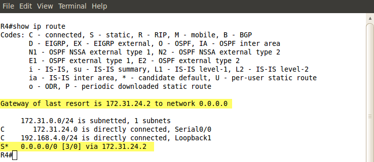
Pic. 12. - R4's Routing Table with Primary Link DOWN.
In the few upcoming posts, I will focus in on dynamic routing protocols.


